
Buck-Boost / Push-Pull Transformers: Efficient Power Conversion Solutions
Buck-boost or push-pull transformers are critical components in power conversion applications. They are widely utilized for converting direct current (DC) voltage into different DC voltage levels and are integral in inverter systems, which convert DC into alternating current (AC). In high-power switching transformer applications exceeding one kilowatt, the push-pull transformer is often the preferred choice.
Understanding Buck-Boost / Push-Pull Transformers
A buck-boost transformer configuration is commonly employed in circuits known as “forward converters.” This versatile transformer can also be referred to as an “inverter,” “DC converter,” or “feed-forward” transformer.
Key Features:
- High Power Capability: Ideal for applications requiring significant power handling.
- Multiple Output Options: Configurations can include tapped secondary windings or multiple secondaries for various voltage outputs.
Operating Principles
The operation of buck-boost transformers can be categorized into two main types: unipolar and bipolar operation.
- Unipolar Operation: In this mode, the core operates within one quadrant of the magnetic B-H loop, maintaining a single polarity throughout the cycle.
- Bipolar Operation: The push-pull transformer operates with both magnetic polarities crossing zero, allowing for greater power handling in a smaller package compared to unipolar designs.
Applications for Buck-Boost / Push-Pull Transformers
- Power Supplies
- Inverters
- Industrial Equipment
Transformer Configurations
1. Push-Pull Transformer Rectification
The push-pull transformer can achieve full-wave rectification using either a center-tap configuration or a full-wave bridge. Each method has its advantages and trade-offs regarding efficiency and complexity.

2. Half Bridge Push-Pull Transformers
This configuration eliminates the primary center-tap, reducing winding capacitance and allowing for efficient operation with a simplified design.
3. Full Bridge Push-Pull Transformers
Similar to the half bridge, this design further optimizes efficiency by eliminating unnecessary components while maintaining performance.

Boost Push-Pull Transformer Applications
In boost applications, inductors are used in conjunction with push-pull transformers to reduce output voltage ripple. This setup allows for effective energy management and improved performance across multiple outputs.
Figure Diagrams
To better illustrate the concepts discussed, we included several key diagrams:
Figure 1: Basic Buck-Boost Transformer Configuration
This diagram shows the fundamental layout of a buck-boost transformer, highlighting the primary and secondary windings along with input and output connections.
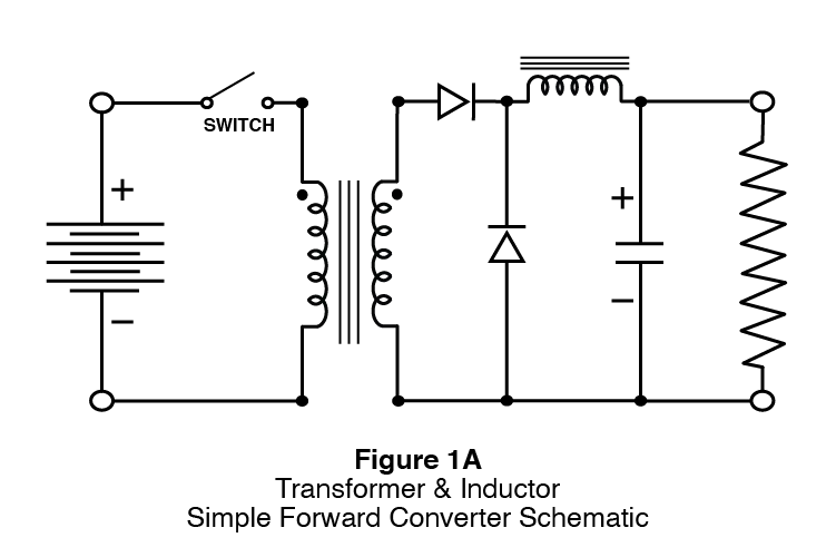

Figure 2: Unipolar vs. Bipolar Operation
This figure compares unipolar and bipolar operation modes, illustrating how each mode affects magnetic flux and power handling capabilities.


Figure 3: Full-Wave Rectification Using Push-Pull Transformer
A detailed diagram depicting how a push-pull transformer achieves full-wave rectification through both center-tap and full-wave bridge configurations.
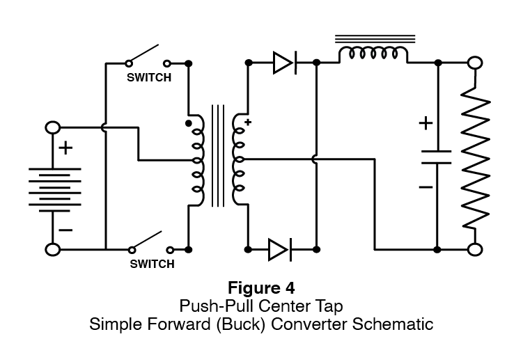
Figure 4 & Figure 5: Half Bridge vs. Full Bridge Configuration
This diagram contrasts half bridge and full bridge push-pull transformer designs, emphasizing their efficiency and component differences.
Conclusion
Buck-boost/push-pull transformers are essential for efficient power conversion in various applications. Whether you need standard transformers or custom solutions, Gowanda Electronics has the expertise to meet your needs. Contact our team today to discuss your requirements and discover how we can assist you with innovative transformer solutions.
Custom Solutions from Gowanda Electronics
At Gowanda Electronics, we specialize in designing custom buck-boost and push-pull transformers tailored to meet specific application requirements. Our extensive capabilities in design, development, production, and testing ensure that we can deliver high-quality solutions that exceed your expectations.