
GLOSSARY
Definitions
A
AC Flux Density (Gauss)
Number of flux lines per unit of cross-sectional area generated by an alternating magnetic field.
Air Core Coil
The term “air core coil” describes an inductor that does not use a magnetic core made of a ferromagnetic material. The coils are wound on plastic, ceramic, or other nonmagnetic forms, as well as those that actually have air inside the windings.
Air Core Inductors (see Ceramic Core and Phenolic Core)
Alternating Current (AC)
Alternating Current describes the flow of charge that changes direction periodically. As a result, the voltage level also reverses along with the current.
Altitude Chamber
Evaluates performance at high altitudes, adhering to MIL-STD-202 standards and custom profiles.
Ambient Temperature
The temperature of still air immediately surrounding a component or circuit. A typical method to measure ambient temperature is to record the temperature that is approximately 1/2 inch from the body of the component or circuit.
Attenuation
The relative decrease in amplitude of a given parameter. Attenuation measurements are common for voltage, current and power. It is usually expressed in units of decibels (dB).
For a power ratio, one dB = 10 Log10 (P1/P2).
A dB is equal to 20 Log20 (I1/I2) for current and 20 Log10 (V1/V2) for voltage ratios.
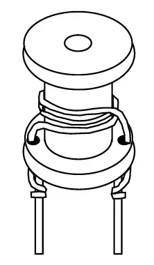
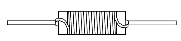
Axial Inductor
An inductor constructed on a core with concentric leads on opposite ends of the core. Axial inductors are available for both power applications and RF applications, and are available in many core materials including the basic phenolic, ferrite and powdered iron types. Both rod and bobbin shapes are utilized. Axial inductors are very suitable for tape and reel packaging for auto placement. (see Inductor)

B
Benchtop Chamber
Versatile testing solutions for various environmental conditions.
Blocking Oscillator
A Blocking Oscillator circuit is a self excited flyback circuit.
Bobbin Core
A core with the shape of a bobbin or spool which contains flanges. Bobbin cores are available with and without leads and in the axial and radial form. (see Axial Inductor and Radial Inductor)
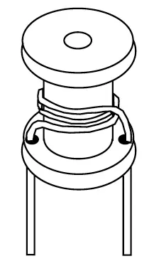
Bobbin Wound Inductor
Bobbin wound inductors refers to a type or method of construction of winding inductors chokes and reactors. Toroidal coils are wound directly onto a toroidal core. The core may be coated or boxed to insulate it from the coil windings. In contrast, bobbin wound inductor coils are wound independently of the core. The coil must hold its shape or form until the coil is assembled onto the inductor core. One common method of doing this is to wind the coil onto a bobbin (also referred to as a spool), hence the term “bobbin wound winding inductor”.
Boost Regulator (DC-DC)
A basic DC-DC switching converter topology that takes an unregulated input voltage, and produces a higher, regulated output voltage. This higher output voltage is achieved by storing energy in an input inductor and then transferring the energy to the output by turning a shunt switch (transistor) on and off.
Bracket
Method of attaching unit to panel chassis which does not provide any electrical connections.
Buck Regulator (DC-DC)
A basic DC-DC switching converter topology that takes and unregulated input voltage, and produces a lower, regulated output voltage. This output voltage is achieved by chopping the input voltage with a series connected switch (transistor) which applies pulses to an averaging inductor and capacitor circuit.
Burden Resistance
Resistance value connected across output terminals to produce required monitoring voltage for AC voltage measuring system.
C
CMF
Gowanda designation for Common Mode inductors, either Surface Mount of Thru-Hole.
Ceramic Cores
Ceramic is one of the common materials used for inductor cores. Its main purpose is to provide a form for the coil. In some designs it also provides the structure to hold the terminals in place. Ceramic has a very low thermal coefficient of expansion. This allows for relatively high inductance stability over the operating temperature ranges. Ceramic has no magnetic properties. Thus, there is no increase in permeability due to the core material.
Ceramic core inductors are often referred to as “air core” inductors. Ceramic core inductors are most often used in high frequency applications where low inductance values, very low core losses and high Q values are required.
Chemical Resistance Testing
Determines durability against various chemicals per MIL-STD-202-215.
Choke (see RF Choke)
Circuit Topology
A generic term used to reference the different types of circuit configurations that may be implemented in a switch mode power supply.
Closed Magnetic Path
Magnetic core shapes designed to contain all of the magnetic flux generated from an excited winding(s). Inductors made with these core types are considered to be shielded inductors. Shielding, however, is a matter of degree. Common core shapes that are considered to have closed magnetic paths are toroids, E-cores and most pot cores. Shielded bobbins also offer a high degree of shielding and may be considered to have closed magnetic paths for most practical purposes. Common core shapes that are considered to have open magnetic flux paths are rod cores and unshielded bobbin cores. (see Shielded Inductor)
Coils
Another common name for inductors. (see Inductor)
Common Mode Choke (CMC)
A common mode choke is a passive electromagnetic device that filters out the unwanted high-frequency noise signal from external sources or other circuits of the system while allowing the desired DC or low-frequency signal to pass. A CMC uses two coils wound on a single core to suppress interference and prevent signal pollution.
Common-Mode Noise
Noise or electrical interference that is common to both electrical lines in relation to earth ground.
Conical
Cone shaped inductor design targeted for high frequency microwave applications.
Copper Loss
The power lost by current flowing through the winding. The power loss is equal to the square of the current multiplied by the resistance of the wire (I2R). This power loss is transferred into heat.
Core
Material placed within and around a coil to support the coil and to play a role in the magnetic flux properties of the inductor.
Core Geometry
Style or types of core structure. Core Geometries have been developed for use in different circuit applications.
Core Loss
Core losses are caused by an alternating magnetic field in the core material. The losses are a function of the operating frequency and the total magnetic flux swing. The total core losses are made up of three main components: Hysteresis, eddy current and residual losses. These losses vary considerably from one magnetic material to another. Applications such as higher power and higher frequency switching regulators and RF designs require careful core selection to yield the highest inductor performance by keeping the core losses to a minimum.
Core Saturation (see Saturation Current)
Curie Temperature
The temperature above which a ferrite core loses its magnetic properties. The core’s permeability typically increases dramatically as the core temperature approaches the curie temperature which causes the inductance to increase. The permeability drops to near unity at the curie temperature which causes the inductance to drop dramatically. The curie point is the temperature at which the initial permeability has dropped to 10% of its original value at room temperature.
Current Output
Output is a current monitored by an ammeter.
Current Rating
The maximum current the inductor can handle at the rated temperature range. Expressed in milliamps (mA) or amps (A) maximum.
Current Transformer Core Type
The core type for a current transformer is usually one of two types, either solid or split. Solid cores are one piece of the desired shape. Split cores are two pieces of the desired shape.
D
DC Current
The unidirectional flow or movement of electric charge carriers. The intensity of the current can vary with time, but the general direction of movement stays the same at all times.
DC-DC Converter
A circuit or device that converts a DC input voltage to a regulated output voltage. The output voltage may be lower, higher or the same as the input voltage. Switching regulator DC-DC circuits most often require an inductor or transformer to achieve the regulated output voltage. Switching regulator circuits can achieve a higher level of power efficiency when compared to non-switching techniques. (see Boost Regulator or Buck Regulator)
DCR (DC Resistance)
The resistance of the inductor winding measured with no alternating current. The DCR is most often minimized in the design of an inductor. The unit of measure is ohms (Ω), and it is usually specified as a maximum rating. This is an undesirable characteristic, which is a by-product of the wire or conductive material used. The lower the DCR, the more current an inductor will handle.
Dielectric Withstanding Voltage (DWV) Testing
Confirms safety and performance under high voltage conditions as per MIL-STD-202-301.
Differential-Mode Noise
Also known as normal-mode noise, it is electrical interference that is not common to both electrical lines but present between both electrical lines.
Distributed Capacitance
In the construction of an inductor, each turn of wire or conductor acts as a capacitor plate. The combined effect of each turn can be represented as a single capacitance known as the distributed capacitance. This capacitance is in parallel with the inductor. This parallel combination will resonate at some frequency which is called the self-resonant frequency (SRF). Lower distributed capacitances for a given inductance value will result in a higher SRF value for the inductor and vice versa. (see SRF)
Duty Cycle
The percentage of time a pulse is on in relation to the switching period: D = t(on) / T(s).
E
Eddy Current Losses
Eddy current losses are present in both the magnetic core and winding of an inductor. Eddy currents in the winding (or conductor) contribute to two main types of losses: losses due to proximity effects and skin effects. As for the core losses, an electrical field around the flux lines in the magnetic field is generated by alternating magnetic flux. This will result in eddy currents if the magnetic core material has electrical conductivity. Losses result from this phenomenon since the eddy currents flow in a plane that is perpendicular to the magnetic flux lines.
EI Laminations
A core structure that is made of usually silicon steel metal pieces shaped like E’s and I’s.
EMI
EMI is an acronym for Electromagnetic Interference. It is unwanted electrical energy in any form. EMI is often used interchangeably with “Noise”.
EMI Frequency Range
Frequency range of interference the choke is to filter.
Epoxy Coated Inductor
Inductors that have been coated with epoxy as opposed to having a molded case, shrink wrapped tubing or left with an open construction body. Epoxy coated inductors typically have smooth edges and surfaces. The epoxy coat acts as an insulation. Both radial and axial styles can be found with epoxy coated surfaces.
Established Reliability
Military approval for axial lead product based on MIL-PRF-39010.
F
Feed Forward
Used in higher powered supplies where a pulse transformer and filter choke are used to convert the input voltage.
Ferrite Core
Ferrite is a magnetic material which consists of a mixed oxide of iron and other elements that are made to have a crystalline molecular structure. The crystalline structure is created by firing the ferrite material at a very high temperature for a specified amount of time and profile. The general composition of ferrites is xxFe2O4 where xx represents one of several metals. The most popular metal combinations are manganese and zinc (MnZn) and nickel and zinc (NiZn). These metals can be easily magnetized.
Ferrite “E” Core
An E shape structure made from dense, homogeneous ceramic materials made by mixing iron oxide with oxides or carbonates of one or more metals such as manganese, zinc, or magnesium. An E-core transformer requires two core pieces per transformer.
Ferrite Toroid
A doughnut shape structure made from dense, homogeneous ceramic materials made by mixing iron oxide with oxides or carbonates of one or more metals such as manganese, zinc, or magnesium.
Filter
A circuit or device whose purpose is to control electrical energy at a given frequency or over a range of frequencies. Groups of passive components are commonly used to construct many types of filters. These passive components include resistors, capacitors and inductors.
Flux
Product of the average component of magnetic induction perpendicular to any given surface in a magnetic field by the area of that surface, expressed in webers.
Flyback Circuit Topology
Common circuit design for low power (<100 Watts) switch mode power supply.
Flyback Transformer
Used in a flyback power supply. Also called horizontal output transformer.
Force Gauge
Measures force application for component strength assessments.
Frequency Range
Range of frequencies over which the inductor is expected to operate.
Full Load Inductance
Inductance under full load conditions.
H
HiPot
Maximum isolation voltage from winding to winding or winding to core/ground.
HiPot Duration
Length of time in seconds to test device at the HiPot voltage.
Humidity Chamber
Tests moisture resistance in accordance with MIL-STD-202-103.
I
Impedance
The impedance of an inductor is the total resistance to the flow of current, including the AC and DC component. The DC component of the impedance is simply the DC resistance of the winding. The AC component of the impedance includes the inductor reactance. The following formula calculates the inductive reactance of an ideal inductor (i.e., one with no losses) to a sinusoidal AC signal.
Z = XL = 2πƒL
L is in henries and ƒ is in hertz. This equation indicates that higher impedance levels are achieved by higher inductance values or at higher frequencies. Skin effect and core losses also add to the impedance of an inductor. (see Skin Effect and Core Losses)
Impedance Analyzer
Test instrument capable of measuring a wide range of impedance parameters, gain and phase angle. In testing inductors, impedance analyzers can measure inductance, Q, SRF, insertion loss, impedance and capacitance. They operate in a much more automatic fashion in comparison to Q Meters. Some impedance analyzers have a wider test frequency range than a Q meter.
Incremental Current
The DC bias current flowing through the inductor which causes an inductance drop of 5% from the initial zero DC bias inductance value. This current level indicates where the inductance can be expected to drop significantly if the DC bias current is increased further. This applies mostly to ferrite cores in lieu of powdered iron. Powdered iron cores exhibit “soft” saturation characteristics. This means their inductance drop from higher DC levels is much more gradual than ferrite cores. The rate at which the inductance will drop is also a function of the core shape. (see Saturation Current)
Inductance
The property of a circuit element which tends to oppose any change in the current flowing through it. The inductance for a given inductor is influenced by the core material, core shape and size, the turns count and the shape of the coil. Inductors most often have their inductances expressed in microhenries (µH). The following table can be used to convert units of inductance to microhenries. Thus, 47 mH would be equal to 47,000 µH.
1 henry (H) = 106 µH
1 millihenry (mH) = 103 µH
1 microhenry (µH) = 1 µH
1 nanohenry (nH) = 10-3 µH
Inductance Tolerance
Standard inductance tolerances are typically designated by a tolerance letter. Standard inductance tolerance letters include:
| Letter | Tolerance |
|---|---|
| F | ± 1% |
| G | ± 2% |
| H | ± 3% |
| J | ± 5% |
| K | ± 10% |
| L | ± 15% * |
| M | ± 20% |
* L = ± 20% for some Military Products
Inductor
A passive component designed to resist changes in current. Inductors are often referred to as “AC Resistors”. The ability to resist changes in current and the ability to store energy in its magnetic field, account for the bulk of the useful properties of inductors. Current passing through an inductor will produce a magnetic field. A changing magnetic field induces a voltage which opposes the field-producing current. This property of impeding changes of current is known as inductance. The voltage induced across an inductor by a change of current is defined as:
V=L di/dt
Thus, the induced voltage is proportional to the inductance value and the rate of current change. (see Inductance)
Input Line Filter
A power filter placed on the input to a circuit or assembly that attenuates noise introduced from the power bus. The filter is designed to reject noise within a frequency band. Typically these filters are lowpass filters meaning they pass low frequency signals such as the DC power and attenuate higher frequency signals which consist of mainly noise.
Bandpass or lowpass filters are commonly made up of inductor and capacitor combinations. (also see Noise, Attenuation, EMI and Pi-Filter)
Input Voltage(s)
The voltage applied to the primary winding.
Iron Core Coil/Transformer
Coil/transformer wound around an iron core to increase its inductance. At radio frequencies the core consists of powdered iron mixed in a binder which insulates the particles from each other.
Isolation Transformer
Transformer with a one-to-one turns ratio, connected between the AC power, input to a piece of equipment and the AC line, to minimize shock hazard.
Insulation Resistance Testing
Evaluates electrical insulation properties following MIL-STD-202-302.
K
Kool MuTM Core
Kool MuTM is a magnetic material that has an inherent distributed air gap. This distributed air gap allows the core to store higher levels of magnetic flux when compared to other magnetic materials such as ferrites. This characteristic allows a higher DC current level to flow through the inductor before the inductor saturates.
Kool MuTM material is an alloy that is made up of basically nickel and iron powder (approx. 50% of each) and is available in several permeabilities. It has a higher permeability than powdered iron and also lower core losses. Kool MuTM is required to be pressed at a much higher pressure than powdered iron material. The manufacturing process includes an annealing step that relieves the pressure put onto the powdered metals which restores their desirable magnetic properties. Thus the powdered particles require a high temperature insulation as compared to powdered iron.
Kool MuTM performs well in power switching applications. The relative cost is significantly higher than powdered iron.
L
LF
Gowanda designation for Lead Free, identifies product compliant with RoHS.
Laminated Cores
Cores constructed by stacking multiple laminations on top of each other. The laminations are offered in a variety of materials and thicknesses. Some laminations are made to have the grains oriented to minimize the core losses and give higher permeabilities. Each lamination has an insulated surface which is commonly an oxide finish. Laminated cores are used in some inductor designs but are more common in a wide variety of transformer applications.
Leakage Inductance
Represents energy stored in non-magnetic regions between windings, caused by imperfect flux coupling.
Life Test Chamber
Conducts longevity tests per MIL-STD-202-108 standards.
Line Frequency
Frequency of line power applied to windings.
Litz Wire
Wire consisting of a number of separately insulated strands that are woven or bunches together such that each strand tends to take all
possible positions in the cross section of the wire as a whole. The current through each individual strand is divided equally since this wire design equalizes the flux linkages and reactance of the individual strands. In other words, a Litz conductor has lower AC losses than comparable solid wire conductors which becomes important as the operating frequency increases. (see Skin Effect)
Load Loss
The power loss or heat generated by current flowing in a winding with resistance.
M
MLRF
Gowanda designation for Military Qualified Radio Frequency inductors.
MLP
Gowanda designation for Military Qualified Power Chokes.
Magnetic Wire
Wire used to create a magnetic field such as those in magnetic components (inductors and transformers). Magnet wire is nearly 100% copper and must be made from virgin copper. It is offered with a number of different organic polymer film coatings.
Matched Impedance
The condition that exists when two coupled circuits are adjusted so that the output impedance of one circuit equals the input impedance of the other circuit connected to the first. There is a minimum power loss between two circuits when their connecting impedances are equal.
Maximum Power Dissipation
An inductor’s ability to handle the heat generated by operating at maximum current at an ambient temperature, expressed in Watts (W) or milliwatts (mW). This is a function of the body area of the inductor and core material used.
Maximum Primary Current
Maximum current flowing through the conductor to be monitored.
MIL-PRF-15305
Military Axial Lead RF inductor specification
MIL-PRF-27
Military Power Choke specification, surface mount and thru-hole.
MIL-PRF-39010
Military Axial Lead RF Hi-Reliability specification.
MIL-PRF-83446
Military Surface Mount RF inductor specification.
MIL-STD-981
Military specification for custom magnetics
MMP Core
MMP is an acronym for molypermalloy powder. It is a magnetic material that has an inherent distributed air gap. The distributed air gap allows the core to store higher levels of magnetic flux when compared to other magnetic materials such as ferrites. This characteristic allows a higher DC current level to flow through the inductor before the inductor saturates.
The basic raw materials are nickel, iron and molybdenum. The ratios are: approximately 80% nickel, 2% – 3% molybdenum, and the remaining is iron. The manufacturing process includes an annealing step as discussed in the Kool Mu® definition. MMP stores higher amounts of energy and has a higher permeability with Kool Mu®. Cores are offered in 10 or more permeability selections. The core characteristics allow inductors to perform very well in switching power applications. Since higher energy can be stored by the core, more DC current can be passed through the inductor before the core saturates. The cost of MMP is significantly higher than Kool Mu®, powdered irons and most ferrite cores with similar sizes. (see Saturation Current)
Moisture Resistance Testing
Evaluates component resilience against moisture as per MIL-STD-202-106.
Molded Inductor
An inductor whose case has been formed via a molding process. Common molding processes include injection and transfer molding. Molded inductors typically have well defined body dimensions which consist of smooth surfaces and sharper corners as compared to other case types such as epoxy coated and shrink wrap coatings. (see Inductor)
Monolithic Inductor (see Multilayer Inductor)
Mounting
The method used to mount the component to the circuit board.
Multilayer Inductor
An inductor constructed by layering the coil between layers of core material. The coil typically consists of a bare metal material (no insulation). This technology is sometimes referred to as “non-wirewound”. The inductance value can be made larger by adding additional layers for a given spiral pattern.
N
Noise
Unwanted electrical energy in a circuit that is unrelated to the desired signal. Sources of noise are mos often generated by some type of switching circuit. Common sources include switching voltage regulators and clocked signals such as digital circuits.
No Load Inductance
Inductance value under no load conditions expressed in micro henries.
No Load Loss (see Core Losses)
Non-Magnetic
Inductor design assuring no magnetic material properties, medical MRI use.
Number of Primaries
Number of Primary Windings. Indicate if center tapped.
Number of Secondaries
The number of secondaries required.
O
Ohm
The unit of measurement for resistance and impedance. Resistance is calculated by Ohm’s Law:
R = V/I
R = Resistance
V = Voltage
I = Current
Operating Frequency
Frequency at which a product will operate.
Operating Temperature Range
Range of ambient temperatures over which a component can be operated safely. The operating temperature is different from the storage temperature in that it accounts for the component’s self temperature rise caused by the winding loss from a given DC bias current. This power loss is referred to as the “copper” loss and is equal to:
Power Loss = I2 x DCR
This power loss results in an increase to the component temperature above the given ambient temperature. Thus, the maximum operating temperature will be less than the maximum storage temperature:
Maximum Operating Temperature = Storage Temperature – Self Temperature Rise
(see Core Losses)
Output Current
Output Current expected to flow through secondary winding(s) under fully loaded conditions.
Output Voltage(s)
Output Voltage expected from secondary winding(s) under fully loaded conditions.
P
Peak Input Current
Maximum peak current flowing through the primary winding.
Percent Saturation
This is equal to 100% minus percent initial permeability. i.e. 20% saturation = 80% of initial permeability.
Permeability (Core)
The permeability of a magnetic core is the characteristic that gives the core the ability to concentrate lines of magnetic flux. The core material, as well as the core geometry, affect the core’s “effective permeability”. For a given core shape, size and material, and a given winding, higher permeability magnetic materials result in higher inductance values as opposed to lower permeability materials.
Phenolic Core
Phenolic is a common material used for inductor cores. Many are made of polyester base that have high temperature characteristics. It is also common for phenolic cores to have high flammability ratings such as UL94V-0. Phenolic cores also provide high strength and are more economical than ceramic cores.
Phenolic has no magnetic properties. Thus there is no increase in permeability due to the core material.
Phenolic core inductors are often referred to as “air core” inductors and are most often used in high frequency applications where low inductance values, very low core losses and high Q values are required.
Pi-Filter
A filter consisting of two capacitors connected in parallel with a series inductor. These filters are commonly found near DC-DC converters to filter ripple current and voltage.
Polyolefin Tubing
A common shrink wrap (tubing) used in the electronic industry. It is often used to provide insulation or protect wire insulation such as coil windings. Polyolefin tubing is a polymer which can be provided to meet various degrees of flammability requirements.
Powdered Iron Core
Powdered iron is a magnetic material that has an inherent distributed air gap. The distributed air gap allows the core to store higher levels of magnetic flux when compared to other magnetic materials such as ferrites. This characteristic allows a higher DC current level to flow through the inductor before the inductor saturates.
Powdered iron cores are made of nearly 100% iron. The iron particles are insulated from each other, mixed with a binder (such as phenolic or epoxy) and pressed into the final core shape. The cores are cured via a baking process. Other characteristics of powdered iron cores include: they are typically the lowest cost alternative and their permeabilities typically have a more stable temperature coefficient than ferrites. (see Saturation Current)
Power Rating
Maximum power expected to process.
Power Transformer
Magnetic-core transformer for operation at 60 hertz, with nearly zero source impedance, to transfer power from line voltage to some required voltage.
Primary Inductance
Inductance in the primary winding.
Primary Winding
The winding connected to the source of energy.
Pulse Duration
The amount of time the pulse is on.
Pulse Repetition Rate
Time from start of a pulse to the start of the next pulse.
Q
Q
The Q value of an inductor is a measure of the relative losses in an inductor. The Q is also known as the “quality factor” and is technically defined as the ratio of inductive reactance to effective resistance and is represented by:
Q = XL/Re = 2πƒL/Re
Since XL and Re are functions of frequency, the test frequency must be given when specifying Q. XL typically increases with frequency at a faster rate than Re at lower frequencies, and vice versa at higher frequencies. This results in a bell shaped curve for Q vs. frequency. Re is mainly comprised of the DC resistance of the wire, the core losses and skin effect of the wire.
Based on the above formula, it can be shown that the Q is zero at the self resonant frequency since the inductance is zero at this point.
Q Meter
A standard instrument used to measure the inductance and Q of small RF inductors. The Q meter is based on a stable, continuously variable oscillator and a resonant circuit which is connected to the part to be tested.
The Q is proportional to the voltage across the internal calibrated variable capacitor. The voltage is measured by an internal RF voltmeter. The capable test frequency range is near 22 kHz to 70 MHz.
QPL (Qualified Product Line)
Identifies a manufacturers military approved product.
R
RoHS (Restriction on Hazardous Substances)
European directive limiting or prohibiting the use of certain materials.
‘R’ Level
Failure Rate Level from MIL-PRF-39010
Radial Inductor
An inductor constructed on a core with leads exiting from the same side of the inductor body as to be mounted in the same plane. Radial inductors most often refer to two leaded devices but technically include devices with more than two leads as well. Some common core shapes include rod cores, bobbins and toroids. (see Inductor)
Rated Current
The level of continuous DC current that can be passed through the inductor. This DC current level is based on a maximum temperature rise of the inductor at the maximum rated ambient temperature. The rated current is related to the inductor’s ability to minimize the power losses in the winding by having a low DC resistance. It is also related to the inductor’s ability to dissipate this power lost in the windings. Thus, the rated current can be increased by reducing the DC resistance or increasing the inductor size.
For low frequency current waveforms, the RMS current can be substituted for the DC rated current. The rated current is not related to the magnetic properties of the inductor. (see Incremental Current and Saturation Current)
Reactance
The imaginary part of the impedance. (see Impedance)
Real-Time X-Ray
Non-destructive testing following MIL-STD-202-209 for internal inspection.
Required Finished Dimensions
The dimensions of the space allotted for the finished product.
RF Choke
Another name for a radio frequency inductor which is intended to filter or choke out signals. (see Inductor)
RFI
RFI is an acronym for Radio-Frequency Interference. It is an older and more restrictive term that is used interchangeably with “EMI”. (see EMI)
Ripple Voltage
The periodic alternating voltage imposed on the voltage output of a switching voltage converter. The ripple voltage is normally specified as a peak-to-peak value.
S
SMD
Gowanda designation for surface mount device.
SMRF
Gowanda designation for surface mount radio frequency inductors
SMP
Gowanda designation for surface mount power chokes
SMT
Gowanda designation for surface mount toroid coils
Salt Spray Testing
Assesses corrosion resistance according to MIL-STD-202-101.
Saturation
Maximum density of magnetic flux that can be present in a magnetic material.
Saturation Current
The DC bias current flowing through the inductor which causes the inductance to drop by a specified amount from the initial zero DC bias inductance value. Common specified inductance drop percentages include 10% and 20%. It is useful to use the 10% inductance drop value for ferrite cores and 20% for powdered iron cores in energy storage applications.
The cause of the inductance to drop due to the DC bias current is related to the magnetic properties of the core. The core, and some of the space around the core, can only store a given amount of magnetic flux density.
Beyond the maximum flux density point, the permeability of the core is reduced. Thus, the inductance is caused to drop. Core saturation does not apply to “air-core” inductors. (see Incremental Current and Permeability)
Secondary Current
Desired output AC current that represents max primary current (AC Ammeter measuring system).
Secondary Winding
The winding is the coil where energy is induced from the primary.
Secondary Voltage
Required output AC voltage to represent max primary current (AC voltage measuring system).
Self Leaded
Inductors that have the internal wire exiting to also form terminals
Self-Resonant-Frequency (SRF)
The frequency at which the inductor’s distributed capacitance resonates with the inductance. it is at this frequency that the inductance is equal to the capacitance and they cancel each other. The inductor will act purely resistive with a high impedance at the SRF point.
The distributed capacitance is caused by the turns of wire layered on top of each other and around the core. This capacitance is in parallel to the inductance. At frequencies above the SRF, the capacitive reactance of the parallel combination will become the dominant component.
Also, the Q of the inductor is equal to zero at the SRF point since the inductive reactance is zero. The SRF is specified in MHz and is listed as a minimum value on product data sheets. (also see Distributed Capacitance)
Shaker System
Test components against MIL-SPEC and custom vibration profiles to ensure reliability under stress.
Shielded Inductor
An inductor designed for its core to contain a majority of its magnetic field. Some inductor designs are self shielding. Examples of these are magnetic core shapes which include toroids, pot cores and E-cores. Magnetic core shapes such as slug cores and bobbins require the application of a magnetic sleeve or similar method to yield a shielded inductor.
It should be noted that magnetic shielding is a matter of degree. A certain percentage of the magnetic field will escape the core material. This is even applicable for toroidal cores as lower core permeabilities will have higher fringing fields than will high permeability toroidal cores. (see Closed Magnetic Path)
Sine Waveform
A signal that varies with time as power the sinusoidal trigonometric function.
Skin Effect
Skin effect is the tendency for alternating current (AC) to avoid traveling through the center of a solid conductor. The current is limited to the surface or “skin” of the conductor (to a level called the skin depth). At higher frequencies the skin effect causes the effective resistance of the conductor to increase which reduces the effective cross-section of the conductor.
Solderability via Steam Aging Chamber
Tests solder joint reliability according to MIL-STD-202-208.
Solid Core Type
Usually round or Toroidal in their shape.
Split Core Type
Usually rectangular in shape but may be Toroidal also.
Square Waveform
A signal made by switching between two voltages at a constant frequency.
Step Up Transformer
When the secondary has a higher voltage than the primary.
Step Down Transformer
When the secondary has a lower voltage than the primary.
Surface Mount
Components manufactured with solder feet that are soldered to pads on the circuit board providing the mounting and connection to the circuit. Electrical connection is made through soldering the component to these solder pads.
T
‘T’ Level
Power choke product QPL to MIL-PRF-27 space level testing.
Terminal Strength Testing
Ensures connection integrity as per MIL-STD-202-211.
Temperature Coefficient of Inductance
(Tc of L) is the value of inductance change as a function of temperature exposure, normally expressed in parts per million per degrees Celsius. This is a calculation comparing inductance at a reference temperature (25°C, room ambient) to the extremes and other temperatures within operating range. Can be called Percent Delta L or Temperature Stability; the lower the change the better for most applications.
Temperature Cycling Chamber
Simulates extreme temperature variations to assess component durability.
Test Frequency
The industry/military standard for testing a range of inductances. It is not intended as the application frequency. Expressed in megahertz (MHz) or kilohertz (kHz).
Thermal Shock Chambers
Complies with MIL-STD-202-107 standards for rapid temperature changes.
Thru-Hole (or Through-Hole)
Component is manufactured with pins that mount the device through holes in the circuit board which are soldered.
Toroidal Core Type
Is a core that is usually round and doughnut shaped.
Turns Ratio (i.e. Ip:Is)
The ratio of the number of primary turns to the number of secondary turns expressed as Np:Ns. Ratio of current monitored to current needed for sensing current.
V
Voltage
Is an expression of potential energy, representing he possibility or potential for energy release as the electrons move from one “level” to another, it is always referenced between two points.
Voltage Range
Range of input voltage that is expected across primary winding.
Voltage Rating
Max output (voltage x current) without core saturation.
W
Waveform
Type of signal that is applied to the input terminals of the transformer.