
To Shield or Not to Shield
A Comprehensive Guide to EMI Shielding in Power & RF Circuit Design
Why EMI Shielding Matters in Modern Electronics
Every electronic device—from smartphones and medical equipment to military and aerospace systems—is vulnerable to electromagnetic interference (EMI). Without proper control, EMI can:
- Cause signal degradation in RF and analog systems
- Increase bit error rates (BER) in digital devices
- Disrupt wireless communication paths
- Lead to non-compliance with EMC standards like FCC Part 15, CISPR, and IEC 61000
As circuits become smaller, faster, and more integrated, shielding and noise mitigation strategies are no longer optional—they’re a fundamental part of electronic design.
What is EMI Shielding?
Electromagnetic shielding reduces unwanted electromagnetic energy by using conductive or magnetic barriers. These shields prevent interference from escaping (emissions) or entering (susceptibility) sensitive circuits.
Radiative vs. Conductive EMI
- Radiative EMI: Coupling through air or dielectric media.
- Conductive EMI: Coupling through physical paths like cables, PCB traces, and connectors.
Measuring Shielding Effectiveness
Shielding effectiveness (SE) is measured in decibels (dB), showing how much EMI is reduced. A high SE = stronger protection.
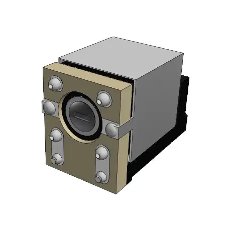
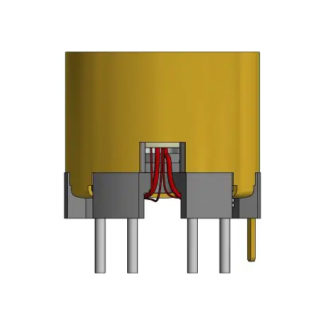
Electric Field Shielding
- Best for high-frequency noise (RF, digital switching).
- Uses thin conductive metals (brass, copper, aluminum).
- Must be designed with minimal apertures to prevent leakage.
- Skin depth effect: thicker shielding may be required at lower frequencies.
- Works best when properly grounded to chassis or system enclosure.
Gowanda offers many shielding solutions, see Figure 1 and Figure 2 for real world examples.
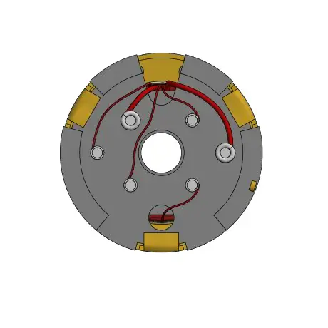
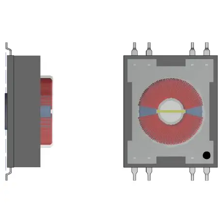
Magnetic Field Shielding
- More critical for low-frequency EMI generated by inductors, transformers, and solenoids.
- Materials: ferrites, powdered iron, Mumetal®, Permalloy®.
- Magnetic shielding effectiveness depends on permeability, thickness, and conductivity.
- Absorption losses convert magnetic energy into heat, reducing EMI.
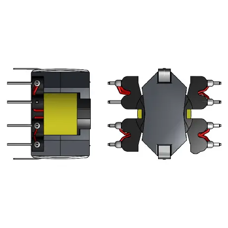
- Core design matters: Toroids, pot cores, and EE cores naturally minimize leakage.
Figure 3 and Figure 4 are real world examples of Gowanda’s Magnetic field shielding capabilities.
Materials for EMI Shielding: Choosing the Right Solution
| Material | Best For | Advantages | Limitations |
|---|---|---|---|
| Copper/Brass/Aluminum | Electric filed shielding | Lightweight, conductive | Less effective at low frequencies |
| Ferrites | High-frequency magnetic shielding | Cost-effective, widely used | Brittle, frequency-dependent |
| Powdered Iron | Power electronics | High saturation, stable at high current | Lower permeability |
| Mumetal® / Permalloy® | Low-frequency magnetic shielding | Extremely high permeability | Expensive, sensitive to stress |
| Nanocrystalline alloys | Advanced high-frequency designs | High performance, temperature stability | Costly, less common |
When NOT to Use Shielding: Smarter Design Choices
Shielding can increase cost, size, and weight. Before adding a shield, consider:
- PCB Layout Optimization: Place inductors and transformers farther apart; mutual inductance decreases with the square of the distance.
- Orthogonal Orientation: Rotate inductors 90° relative to each other to reduce coupling.
- Closed Magnetic Paths: Use toroids or pot cores to naturally self-shield.
- Winding Strategy: Connect the start lead to switching nodes to minimize radiation.
These design tricks often reduce EMI without the expense of external shields.
EMI Testing & Compliance
Testing shielding effectiveness should occur throughout product development:
- Component level → evaluate inductors, transformers, and chokes.
- Circuit level → test PCB trace layouts and grounding strategies.
- System level → ensure compliance with MIL-PRF-83446D and other standards.
Example: Using the Percent Coupling Method, a shielded inductor achieving <3% coupling is considered excellent.
Industry Applications for EMI Shielding
- Medical Electronics: Shielding ensures compliance with IEC 60601 standards for patient safety in imaging and monitoring devices.
- Aerospace & Defense: MIL-PRF-qualified components withstand extreme environments and strict EMI standards.
- Automotive & EVs: EMI shielding reduces noise from high-power switching (inverters, chargers) in ADAS and infotainment systems.
- Consumer Electronics: Smartphones, wearables, and IoT devices demand shielding solutions that work in tight, miniaturized layouts.
Cost vs. Performance Tradeoffs: Shielded vs. Unshielded Inductors
| Factor | Shielded Inductor | Unshielded Inductor |
|---|---|---|
| EMI Reduction | High | Low |
| Size & Weight | Larger | Smaller |
| Cost | Higher | Lower |
| Efficiency | Slightly reduced | Higher |
| Reliability in EMI environments | Excellent | Limited |
Comparison to Other EMI Mitigation Techniques
Shielding is only one piece of EMI management. Other strategies include:
- Filtering (LC filters, ferrite beads, common-mode chokes)
- Ground planes & stitching vias for low-impedance return paths
- Differential signaling to cancel noise
- Cable shielding & twisted pairs for noise rejection
Often, shielding + filtering gives the best performance.
Gowanda Shielding Solutions
Gowanda provides both standard and custom magnetic components designed for EMI reduction and compliance.
Featured Shielded Inductor or Choke Series:
- ER17S Axial Inductor – Space-level qualified, rugged, reliable up to 100 MHz.
- SMRF3013S SMT Inductor – Precision iron-shielded design for high-reliability applications.
- SMRF1512S SMT Inductor – Ferrite-shielded, high-Q design for VHF and UHF wireless systems.
- SMRF1812S SMT Inductor – Configurable as shielded or unshielded, offering design flexibility.
- CMF61SM Common Mode Chokes – Excellent self-shielding for power EMI filters.
Best Practices for EMI Shielding in PCB Design
- Plan shielding early in the design cycle.
- Combine shielding with filtering (capacitors, ferrites, common mode chokes).
- Use ground planes and vias to control return paths.
- Validate in real-world conditions (temperature, vibration, power fluctuations).
- Balance tradeoffs: shielding vs. efficiency, size, and cost.
Frequently Asked Questions (FAQ)
What’s the difference between electric and magnetic shielding?
Electric shielding blocks high-frequency electric fields using conductive enclosures. Magnetic shielding diverts low-frequency flux into high-permeability paths, reducing radiation.
Does EMI shielding increase power consumption?
Minimal, but some shields introduce losses due to eddy currents.
Can layout design replace shielding?
In many cases, yes. Proper inductor spacing, orientation, and PCB layout can eliminate EMI problems without physical shields.
How do I know if I need shielding?
If EMI tests show excessive emissions or susceptibility—even after layout optimization—shielding is the next step.
What materials work best for EMI shielding?
- Electric shielding: copper, brass, aluminum.
- Magnetic shielding: ferrites, powdered iron, Mumetal®.
How do EMI shields affect efficiency?
Shields can slightly reduce efficiency due to eddy currents and absorption losses, but tradeoffs are often worthwhile for compliance.
Can EMI shielding improve wireless performance?
Yes—by reducing self-interference, shielding improves antenna sensitivity and signal integrity.
Conclusion
Electromagnetic shielding remains one of the most effective tools for controlling EMI. But shielding is not always the first or only solution. By combining smart PCB design, material choice, testing, and compliance planning, engineers can achieve both performance and efficiency.
At Gowanda, we specialize in shielded and unshielded inductors, transformers, and EMI suppression solutions designed to help you achieve EMC compliance while meeting size, cost, and reliability goals.