
MAGNETIC AMPLIFIER THEORY
The following information is provided as a basic overview of how a typical simple mag amp functions. Rectifier aided mag amp circuits are not discussed. If you require more information please contact Gowanda.
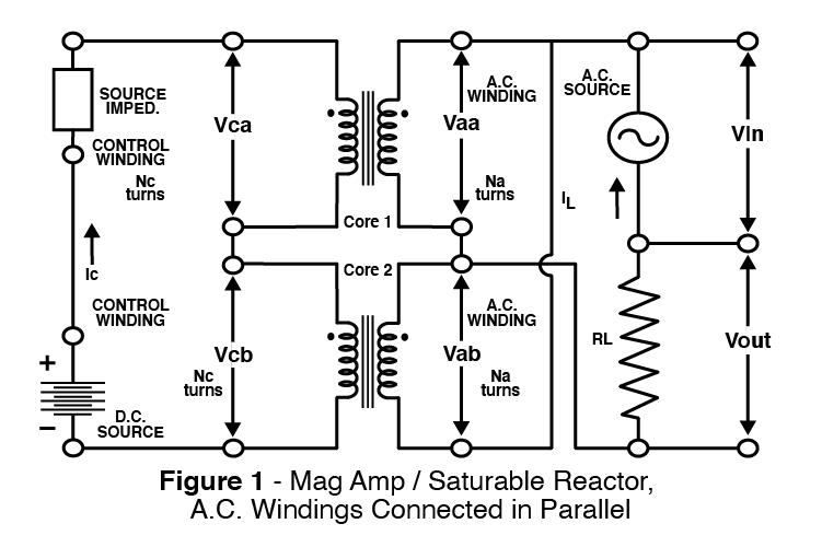
Refer to the schematic of Figure 1 bearing in mind (in theory) that the two coils have identical windings and identical cores. Because of transformer action, the A.C. voltage impressed across the mag amps A.C. windings will induce a voltage across each control winding. Because of the opposite phasing of the A.C. windings, the induced voltages in the D.C. windings will buck each other and exactly cancel each other (in theory) resulting in zero A.C. voltage induced across the D.C. source. Consequently, the low impedance D.C. source will not load down the A.C. windings.
Consider the impedance of the A.C. windings with no D.C. current supplied. The core and windings are designed such that:
- the core does not saturate at the maximum intended A.C. voltage, and
- each A.C. winding has a relatively much higher impedance than the intended load.
Because of the high impedance, very little A.C. current flows. Consequently, there is very little voltage drop across the load. Now consider the impedance of the A.C. windings with a D.C. current flowing through the control winding. Both cores have a D.C. biasing flux of equal value and the same phasing. The A.C. windings of Figure 1 are connected in parallel but with opposite phasing. The total flux in a core is the sum of the D.C. flux and the A.C. flux. Because of the opposite A.C. winding phasing, the A.C. voltage increases the core flux of one core while decreasing the core flux of the other core until saturation occurs. Eventually the alternating fashion of the A.C. voltage causes the changing flux to reverse the direction of flux change of both cores. Now apply enough D.C. current to cause one core to enter saturation. The core’s flux reaches its maximum values and does not change (ideal theory) while in saturation; hence no induced voltage will oppose the applied A.C. voltage. The impedance of that core’s A.C. winding drops to near zero value. There can be very little voltage drop across that A.C. winding. The other A.C. winding is connected in parallel to this A.C. winding. This A.C. winding shunts the current around the other A.C. winding hence the other A.C. winding also sees very little voltage impressed across it. Consequently the flux of the other core changes very little (essentially stays where it is). While a core is saturated there is very little impedance between the A.C. voltage source and the load impedance. Consequently significant load current flows during saturation and produces a relatively large voltage drop across the load. Because of the eventual A.C. voltage reversal, the saturated core will eventually come out of saturation, high A.C. winding impedance will occur again, and the load current will again drop to near zero value. Eventually the other core saturates resulting in high load current until the core leaves saturation. The mag amp has seen a complete A.C. cycle and will proceed to the next cycle. For mag amps, entering saturation is like closing a switch. The time spent in saturation is the turn-on time of the mag amp switch.
The amount of time spent in saturation is determined by the amount of D.C. biasing current. A larger D.C. bias current causes the cores to enter saturation earlier and exit saturation later, thereby increasing the length of time current is delivered to the load, thereby increasing the average amount of current delivered to the load in a given period of time. Once a steady state condition is reached in an idealized mag amp, it can be shown that the averaged ampereturns of the load current are proportional to the ampere-turns of the control current. With appropriate choices of turns ratio, windings, and cores, one can achieve significant power amplification gain.
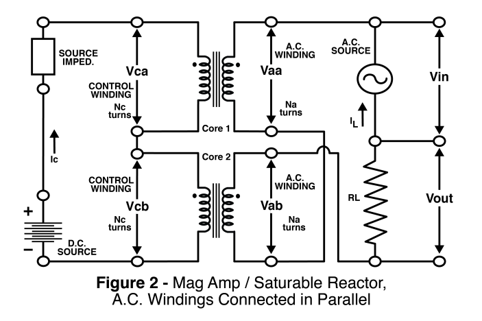
The schematic in Figure 2 shows the A.C. windings connected in series. When one core saturates both of its winding have relatively very low impedance and can be ignored. The core’s A.C. winding does not shunt the other A.C. winding, but the other A.C. winding will not maintain its high impedance level if the D.C. source has a sufficiently low impedance. With one core saturated the low impedance D.C. source becomes a transformer-coupled load to the unsaturated A.C. winding. The impedance on the unsaturated A.C. winding drops to the transformer coupled reflected value of the low impedance D.C. source.A load current flows which produces a significant load voltage.
Quick Menu
Questions or Concerns?