Pulse Distortion

PULSE DISTORTION

Application Notes > Pulse Distortion

Ideally the output pulse waveform should be identical in shape to the input pulse waveform except for a desired amplitude change due to the step-up or step-down turns ratio. Any other deviation is considered to be distortion. Rise time, droop, trailing edges, and spurious oscillations are all considered to be signal distortions.

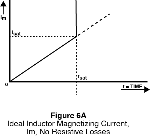
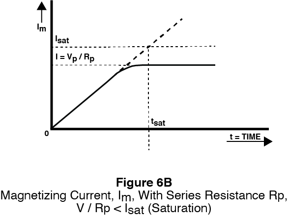
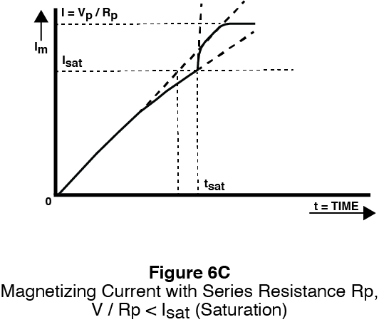
Figure 6A, 6B and 6C illustrate various types of distortion. The trailing edge is further described below.

Figure 6A depicts an inductor that saturates, with no current limit. The following information is also relevant: Im = I0 + Vp x t/L I0 = 0; Rp = 0; and Lm + Lkp = L (referring to Figure 2B above)

Figure 6B depicts an inductor that does not saturate and is current limited. The following information is also relevant: Im = I0 + Vp x e(-Rp/L)t/L I0 = 0; Rp = 0; and Lm + Lkp = L (referring to Figure 2B above)

Figure 6C depicts an inductor that saturates, but is current limited. The following information is also relevant: Im = I0 + Vp x e(-Rp/L)t/L I0 = 0; Rp = 0; and Lm + Lkp = L (referring to Figure 2B above) And the inductance L changes at Isat