
CURRENT TRANSFORMER THEORY
In the typical current transformer application, the primary winding consists of one to a few turns of wire. The primary wire size is much larger than the secondary wire size. The number of secondary winding turns is a selected multiple of the primary turns. Figure 1 gives a circuit schematic of a current transformer application.
Electro-Magnetic Interference (E.M.I.)
E.M.I. in the circuit’s environment is one source of electrical noise. E.M.I. induces Common Mode Choke or couples unwanted electrical signals into the circuit. It is Product Page desirable to filter out the unwanted noise signals without significantly affecting the desired signal. Environmental sources Power Inductors, Chokes of E.M.I. often create an independent return path (ground path) & Reactors FAQs for the electrical noise signals. The return path of the desired signal is a different path. Because there are two different return paths, a Common Mode Choke can be used to significantly block (hence reduce) the unwanted noise signal (at the load) without significant reduction in the desired signal.

The current transformer shown represents an ideal transformer. The ideal transformer has infinite no-load input impedance, 100% magnetic coupling between transformer windings (hence no leakage inductance), zero winding resistance, zero core losses, and no capacitance. (Capacitance, leakage inductance, winding resistance, and core losses are considered to be parasitic components.) The output voltage is exactly proportional to the primary voltage times the turns’ ratio. There is no regulation drop. There are no losses. Since there are no parasitic components the ideal current transformer is 100% accurate. The conservation of energy requires that the output power equals the input power, hence Vp x Ip must equal Vs x Is. Since Vs = Vp x Ns / Np, it can be shown that Is = Ip x Np / Ns. Is = Vs / RL, hence Ip = Ns x Vs / ( RL x Np ). With an ideal current transformer there is no phase shift (except 180 degrees depending on the choice of output connections).
The ideal transformer’s secondary resistive load consumes power equal to Is x Is x RL. This same amount of power must be consumed at the primary terminals. The secondary load RL can be replaced (commonly referred to as reflected) with a resistor across the primary terminals, RLr. By applying the conservation of energy, one can show that RLr equals Np x Np x RL / (Ns x Ns), OR RLr equals RL times the turns ratio squared (where turns ratio = Np / Ns). If Np / Ns is small, then the RLr is very small. The primary voltage drop is Ip x RLr. A very small value for RLr means that the current transformer presents a low insertion loss to the primary current and a low primary voltage drop.
The reflected load impedance acts in parallel to the transformers own input impedance. The ideal current transformer has infinite input impedance. This infinite impedance would correlate to an infinite inductance inserted in series into the path of the primary conductor. Without the load (or burden) the current transformer acts like an inductor and would completely block the primary current flow. Any constant value of alternating current would, in theory, produce an infinite primary voltage drop. In reality the current transformer’s input inductance (hence also impedance) cannot be infinity. The current transformer has an inductance value which acts in parallel to the reflected load. The core has losses that can be represented as a resistor in parallel with the reflected load and the transformer’s self-inductance (no load inductance). Without the load resistor the inductance and core loss will place an upper limit on the primary voltage, but this voltage could still be substantial. Core saturation is also a possibility. A turns ratio step-up would result in even higher secondary voltage. Any circuitry beyond the secondary load resistor could be subjected to high voltage, possibly resulting in circuit damage. Because of this potential high voltage, the load resistor should never be removed from the secondary when the current transformer is being powered.
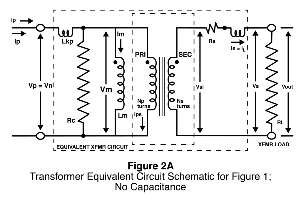
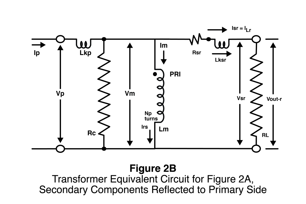
Figure 2A shows an equivalent circuit schematic for a current transformer with load RL. The ideal (induced) secondary voltage is now denoted as Vsi and Vs now denotes the voltage at the secondary terminals. Notice that the schematic contains the ideal current transformer and load as before plus transformer mutual inductance Lm, secondary winding resistance Rs, core loss resistor Rc, secondary leakage inductance Lks, and primary leakage inductance Lkp. Just like for the load resistor, the other secondary circuit components can be reflected to the primary side of the transformer. This is illustrated in Figure 2B.
The parasitic components, Rs, Lkp, and Lks, all act to lower the output voltage across RL, hence the output voltage, Vout, will not equal the induced secondary voltage Vsi. Rs and Lks act in series with RL and are reflected to the primary side along with Rs. Their presence presents added impedance to the primary current hence an increase in primary voltage in proportion to the impedance. Consequently, RL still has the same voltage drop and current flow as it did without Lks and Rs even though Vs does not equal Vout. The phase shift associated with Lks will cause some slight deviation from the ideal current ratio (which equals the turns ratio).
The current transformer’s self (no-load) inductance Lm and the core loss Rc shunt current away from the reflected load and reflected parasitic components. Their impedances act in parallel to the reflected impedances, consequently lowering the impedance seen by the primary current and the resulting primary voltage. Less primary voltage means less output voltage and less secondary current. Consequently Lm and Rc also cause deviation from the ideal current ratio.
As long as Rc, Lm, Lkp, Lks, and Rs are constant in value, The actual current ratio will be some fixed ratio times the ideal (or desired) current ratio. One can compensate for the deviation from the desired current ratio by appropriate choice of secondary turns. The number of turns will be a little lower than that for the associated ideal turns ratio. For constant values accuracy could be 100% except for any turn resolution limitations (full turns versus fractional turns).
Accuracy concerns arise from non-constant values for Rc, Lm, and to a lesser degree from Lkp and Lks. These values usually vary with core induction levels; hence they vary over the range of primary current being measured. (Air core transformers are stable but magnetic coupling is relatively poor hence relatively large leakage inductances.) Since Rc and Lm impedances act in parallel to the reflected load, higher Rc and Lm values have a smaller effect and consequently increase accuracy. Cores materials with high permeability and low core loss are preferred for high accuracy applications.
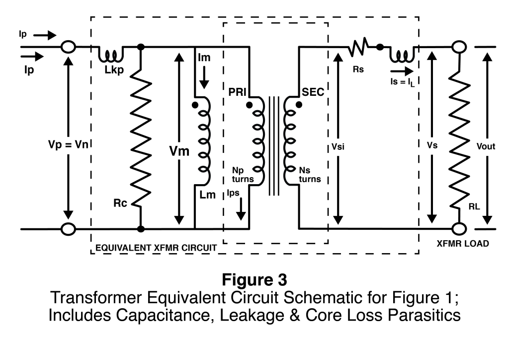
At higher frequencies winding capacitance becomes a concern. Figure 3 gives an equivalent circuit schematic, which includes winding capacitance. Leakage inductance and winding capacitance are actually distributed components, but are shown as lumped approximate equivalent components. Like Lm, winding capacitances shunt current around the reflected load. The inductances and capacitances can interact and consequently may produce spurious oscillations. It is also possible to develop parallel resonance. High frequency coil designs seek to minimize winding capacitances.
CL = Load (Storage/Filter) Capacitor Cp = Primary Winding Self Capacitance & Winding to Winding Capacitance Cs = Secondary Winding Self Capacitance Lm = Transformer Mutual Inductance Lkp = Primary Leakage Inductance Lks = Secondary Leakage Inductance Lksr = Secondary Leakage Inductance = Np x Np x Lks / (Ns x Ns) Rc = Resistance Representing Core Loss Rd = Diode Effective Resistance RL = Load Resistance RLr = Reflected Load Resistance = Np x Np x RL / (Ns x Ns) Rp = Primary Winding Resistance Rs = Secondary Winding Resistance Rsr = Reflected Secondary Winding Resistance = Np x Np x Rs / (Ns x Ns) Vout-r = Vsr = Reflected Secondary Voltage = Np x Np x vs / (Ns x Ns)
Quick Menu
Questions or Concerns?