
POWER TRANSFORMER OPERATING THEORY
The Ideal Transformer
To better understand power transformers it is important to become familiar with the concept of an ideal transformer. An ideal transformer has no parasitic losses (no core loss, no winding resistance, and no leakage inductance). Ideal transformers are 100% efficient. An ideal transformer has infinite input impedance hence the ideal transformer does not draw any current for itself. Primary current equals zero. Figure 1A shows the schematic on an ideal transformer with primary turns Np and secondary turns Ns.

In the ideal (and the typical) electronic transformer, the primary and secondary windings share the same core and see the same amount of magnetic flux. Due to the applied alternating voltage, the magnetic flux is repeatedly changing value and the direction (polarity) of”flux change” is repeatedly reversing its direction. This change in flux induces a voltage in each of the transformer winding turns equal to the primary voltage, Vp, divided by the number of primary turns, Np. The total induced primary voltage equals and opposes the applied primary voltage. The induced primary voltage limits the flow of primary current. In the ideal transformer the current value is zero. In non-ideal transformers this current is greater than zero. This current is known as the magnetizing or exciting current. The induced secondary voltage, Vs equals the number of secondary turns times the induced voltage per turn. or equivalently, Vs = Ns x Vp / Np.
Figure 1B shows the schematic of the ideal transformer with a resistive load placed across its secondary terminals.

Since there are no transformer losses, power in equals power out. The induced secondary voltage, Vs causes current, Is, to flow through the resistive load and secondary winding. The direction of current Is acts to lower the induced primary voltage which opposes the applied input primary voltage. Consequently more primary current flows. The value of the primary current increases until it causes the opposing induced primary voltage to equal the applied input primary voltage. Conservation of energy requires that power out to equal power in hence Ip x Vp = Vs x Is, or Ip = Vs x Is/ Vp. Since Vs = Ns x Vp / Np, Ip can be rewritten as Ip = (Ns x Vp / Np) x Is /Vp, or equivalently, Ip = Ns x Is/ Np, or Ns x Is = Np x Ip. In an ideal transformer, Ip is the secondary winding’s load current reflected (transformed) to the primary winding. The effective primary impedance, Zp = Vp /Ip.It can be shown that Zp = Np x Np x Zs/ (Ns x Ns), where Zs = the secondary load impedance. This equation also holds for inductive and/or capacitive loads.
The Non-Ideal Transformer
Figure 2 shows an equivalent circuit schematic (electrical model) of a non-ideal power transformer. Leakage inductance and winding capacitance are actually distributed circuit elements. The schematic represents leakage inductance and capacitance as lumped circuit components. In effect, the distributed elements are transformer coupled into equivalent collective lump sum values. Bear in mind that the lumped values will only approximate real life conditions. At sufficiently low frequencies, the impedance of the capacitors become sufficiently high to permit ignoring their effect. The capacitors can be removed for low frequency designs.
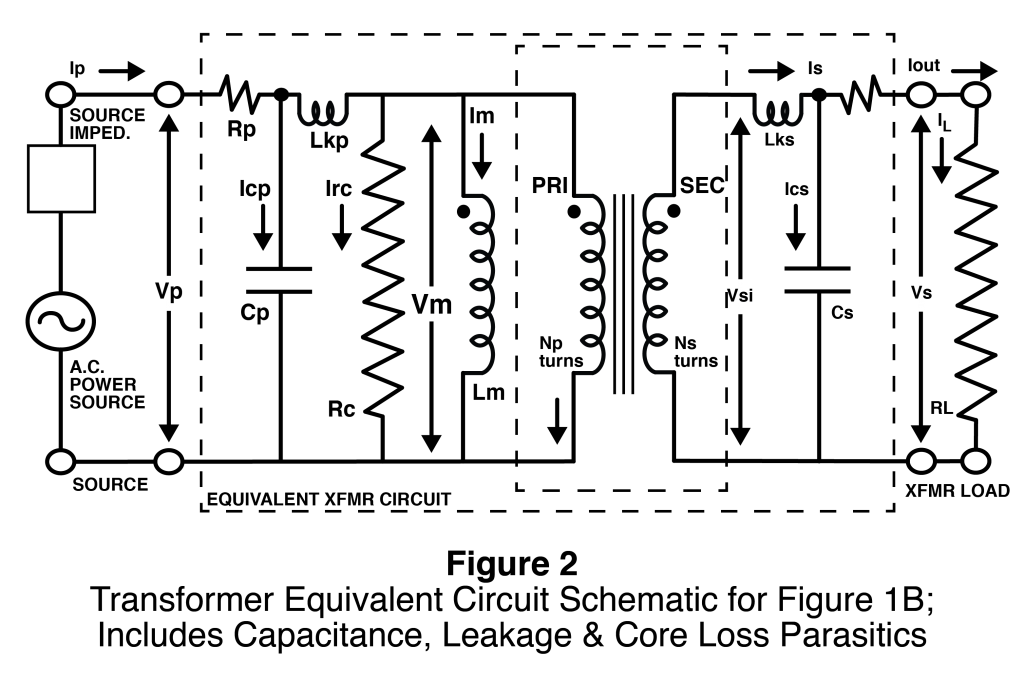
The voltage drop Vm across the mutual inductance, Lm, represents the induced primary voltage. Voltage drops occur over parasitic components Rp and Lkp when current flows through them. Consequently the induced primary voltage, Vm, is less than the voltage Vp applied to the primary terminals. The secondary induced voltage, Vsi, becomes less than that of an ideal transformer. In similar fashion, voltage drops occur over parasitic components Rs and Lks when current flows through them. The secondary terminal voltage, Vs, becomes less than the secondary induced voltage, Vsi. These voltage drops are known as regulation drops. The decline in secondary output voltage from its no load voltage with increasing load current is known as transformer regulation. Percent voltage regulation equals 100% (no load Vs – full load Vs)/ full load Vs.
Magnetizing Current and Saturation
Transformer designs must avoid core saturation. Saturation occurs when the applied ampere turns (Np x Im in Figure 2 above) generates more magnetic flux than the core can handle. The reflected secondary load current, lrs in Figure 2, does not contribute to saturation. Nor does lcp or Ire. The magnetizing current, Im, must be held below the value where Np x Im causes saturation. Np x Im is also known as the magnetizing force. Saturation can be avoided by applying the following formulae V = 4 x F x Bm x N x Ac x Sf x f where; V = r.m.s voltage in volts, F = form factor for the voltage waveform (unitless), Bm = maximum allowed flux density in Telsa, N = the number of turns, Ac = the core’s cross sectional area seen be the winding in square meters, Sf is the stacking factor of the core (unitless ratio< or = to 1), and f = the operating frequency in hertz. The value of Bm depends on the saturation valve of the particular type of core material that will be used, and on the maximum heat the core can be permitted to generate. The latter is dependent on operating frequency.Additional information about saturation is provided in the pulse transformers section.
Bipolar Operation
The cores in A.C. power transformers are usually operated in bipolar mode, but could be operated in unipolar mode by using a D.C. biasing current through a transformer winding. Additional information about bipolar and unipolar operation is provided in the buck boost transformers and pulse transformers section.
Gowanda designs and manufactures electronic transformers and power transformers in a wide variety of materials and sizes. This includes: various standard types of core with bobbin structures (E, EP, EFD, PQ, POT, U and others), toroids and some custom designs. Our upper limits are 40 pounds of weight and 2 kilowatts of power. Our capabilities include foil windings, Litz wire windings and perfect layering. For toroids, the list includes sector winding, progressive winding, bank winding and progressive bank winding. Gowanda has a variety of winding machines, including programmable automated machines and a taping machine for toroids. Gowanda has vacuum chambers for vacuum impregnation and can also encapsulate. To ensure quality, Gowanda utilizes programmable automated testing machines. Most of our production is 100% tested on these machines.
Quick Menu
Questions or Concerns?